There are two kinds of antenna rotators:
1. Those that have failed.
2. Those that will.
Wind, weather, and time eventually degrade and damage every rotator, no matter how robust the design. I've repaired quite a few over the years. Here are some service guides and random advice.
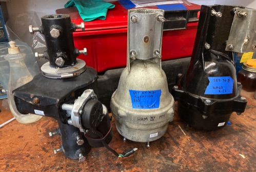
Hy-Gain "Ham" series, including the T2X Tailtwister
T2X Maintenance Manual (not 100% complete but very useful)
Good website on how to rebuild a T2X by K5LAD
Another good T2X rebuild blog by VE3VN
All the classic bell-housing Hy-Gain rotators use the same motor and gear train. The main difference is the housing, with the T2X being more robust. So the instructions are fairly universal.
If you need parts, look up the part numbers in the user manual as best you can, then call the parts department at MFJ at 662-323-9538. As of late 2023, the guy there is Tom Stone, AA5MT, and he is quite knowledgeable. Here are some guides that I use all the time:
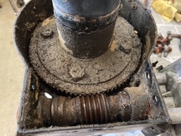
Alfa Spid RAK... A bit gritty, eh?
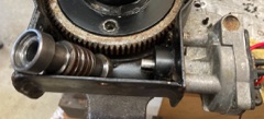
T2X after servicing. Much mo betta.
Alfa Spid RAK and BIG RAK
We have a number of these in use at N6RO and they are quite robust. The failures I've seen are worn-out motors, worm gear getting pushed away from the main gear, and a motor with shorted windings. One also suffered a cracked body, but the worm gear was also bent, making it unsalvageable. There is no service info published on these. So here are some notes.
If you need parts, good luck. The one place that has anything at all is also my favorite place to buy these rotators because of their excellent prices and fast international delivery: The DX Shop in the UK, https://thedxshop.com/ Search for SPID and you will find some parts, specifically the motor assemblies. They have videos showing how to replace those motors but it's not as easy as it seems.
Diassembly Procedure
1. Remove the rain shield, held on by a worm-drive hose clamp. It comes off in two pieces.
2. Remove the top cover, held on by one nut and couple of sheet metal screws.
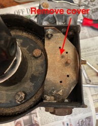
3. Remove the plate covering the worm gear, held on by 3 bolts (little RAK only).
4. Remove the large nut on the outside of the worm gear. Requires a large wrench. Best to hold the base of the rotator in a vise while man-handling this.
5. Unscrew the bearing cone from the inner nut.
At this point, the worm gear will become loose enough to be removed. There are loose ball bearings at each end that you will have to fish out. If the balls need replacement, note that they are a metric size.
I do not know of a practical way to access the large primary bearings inside this rotator.
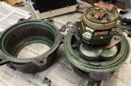
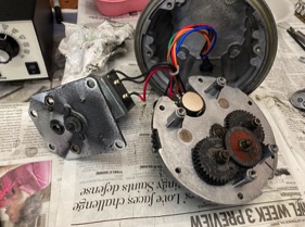
Motor Removal and Checking
To do a thorough job of cleaning the bearing races, it's best to remove the motor assembly but be warned: It's awkward. See the slightly out-of-focus videos on the DX Shop website (Also on YouTube). There are 3 screws that hold it on, but the 2 on the inside of the housing of the (little) RAK are at very difficult locations to access with a screwdriver. (I sometimes replace them with metric socket head screws, but those have to be altered on a lathe because the heads too large.) The BIG RAK only has one screw inside and it's fairly easy to access.
Once the motor is removed, you can clean all the bearings easily.
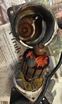
Check the motor for internal corrosion and also the brush condition. To do this, the black cylindrical motor housing must be removed. There are 2 screws that hold it on. Then it slips off. There will be resistance from the bearing that's let into the far end of the housing; pull HARD. The motor shown here was completely frozen due to rust in that bearing. It was unusable. Sometimes the brushes are completely worn down, and the housing may be full of carbon dust. In any case, you have to buy the whole new motor/gearhead assembly.
Reassembly Procedure
1. Grease the big main gear teeth.
2. Pack both bearing races with grease and insert the ball bearings. Tweezers may help.
3. Place the bearing cone with its internal nut into position, backed out as far as it goes.
4. Coat the worm gear with grease, and slip it into position. Make sure not to knock any balls out of place.
5. Thread the bearing cone in until the bearing start to snug up, then install the outer lock nut. The worm gear should turn nice and smooth. SEE INFO BELOW ABOUT AN OPTIONAL UPGRADE.
6. Install the cover plate over the worm screw and tighten all 3 bolts. This MUST be in place before adjusting the bearing because it pulls in the sides of the housing.
At this point, you're ready for the critical drive train adjustment. You should fabricate a spanner wrench to fit the end of the worm gear shaft. I made mine from 1/8 inch band iron, bent at 90 deg and hack sawed to fit. (The hole has nothing to do with it... this was a piece of scrap.)
Upgrade...
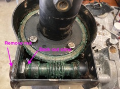
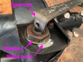
As I mentioned, a failure mode of this rotator is that the worm gear gets pushed away from the main gear. Only the friction of the big locknut keeps it in place. My upgrade is this: Add a big, thick washer that CLOSELY fits the bearing cone, and when all the final adjusting is done, weld it in place. I used some generic steel washer and bored it to exact size on my lathe.
Back to Adjusting
You have two goals: Maintain small clearance between the worm and the big gear, and minimal slop in the worm gear bearings. Everything needs to turn nice and smooth without rattling. If the motor is removed this is much easier since you can spin the worm with your fingers. Otherwise you can only feel the smallest of motion.
The inner nut will not turn; it's blocked in place by a welded tab, thank heavens, but it will wiggle a bit. Get everything finger tight, and maybe a little beyond with a big wrench and keep evaluating the clearances. Use the spanner to counter the wrench torque. Much trial and error may be required. The lock nut needs to be VERY tight, especially if you don't do the welded washer upgrade.
Final Assembly
1. Reinstall the motor, if removed. You'll see the fork in the shaft that must align with a pin inside the worm gear. Good luck with the motor screws! Make sure they are tight. NOTE: You will have to temporarily remove the cover plate to install the inner screws. As I said, it's easier to do all the adjustments with no motor, but that plate needs to be there at that time, and now it's in the way... Bit of a Catch-22.
2. Test the motor operation.
3. Install the top cover.
4. Install the rain shield. I like to coat all the mating surfaces with silicone caulk to help keep water out. When tightening the worm clamp, make sure that the shield is just barely above the rim of the top cover, and not touching.
Sealing of the motor and its terminal housing is another weak spot on this rotator. I use silicone caulk everywhere that makes sense. There should be a copule of small drain holes in the bottom of the motor cover, be sure those are open.
When you're all done, consider applying a label showing the maintenance date. I use a Brother labeler and they seem to last a very long time in the sun. For Hy-Gain rotators, I make sure they're centered at North, and labeled as such.
A Happy Family.
Yaesu G800, G1000, G2800 Family
There is one service manual that I am aware of for Yaesu rotators. It has an exploded view, a parts list, and a schematic for a controller. Here are two resources that I have found useful when working on them: First is a Facebook group (I HATE Facebook but was force to join this one...). The second is a nice fellow in Australia (Duoro Services) who does repairs and has posted some YouTube videos. He is also active on the Facebook group. If your controller is sick, there are some random YouTube videos dealing with that as well.
My personal experience is limited to the G-2800DXA which I found to be very well designed and built, far superior to the Hy-Gain models. They are pretty easy to service just by observing how things come apart. Getting the pot synchonized with rotation is tricky. WC0M has a web page devoted to repairing a G-1000DXA that includes some tips on this subject. The three main models are very similar.
As for parts, the main source is the manufacturer, Vertex Standard, phone number: 714-827-7600 (ask for parts). A supplier in the Netherlands has quite a few Yaesu parts for sale. The Australian fellow also has a small stock of parts for sale and is probably worth contacting.
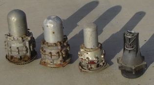
Prop Pitch Rotators
The king of rotators is the prop pitch, a gearmotor recycled from aircraft. I have not worked on one myself but here is some information. With the passing of experts K7NV and K2QVB, we are left only with some online resources.
General description from the old K7NV web pages
Green Heron Engineering RT-21PP rotator controller for prop pitch