I admit it, I’m a test equipment junkie.
My fascination with measurement systems and techniques goes way back to early high school. I was always building electronic stuff, starting with model railroad controls, an “all-american five” tubed radio, and of course ham equipment, and also audio gear. Test equipment is a natural requirement for any of those areas. But more than that, I ended up becoming a specialist in the EE world, an instrumentation engineer. Measuring and controlling things of all kinds became my passion. Here’s an overview of the gear that I have now. I’ll try to generate public documents of more of my homebrew boxes as time permits. Many are derived from published designs, and I’ll point you to those.
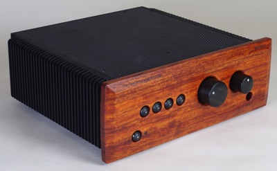
By the way, I also built a lot of audio equipment over the years. See what my Final Integrated Amplifier is all about.
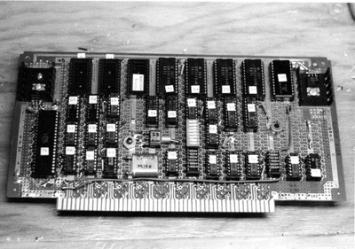
Every electronics guy has his nose in computers, and here's the story of the first one that I built during college.
Commercial Test Equipment
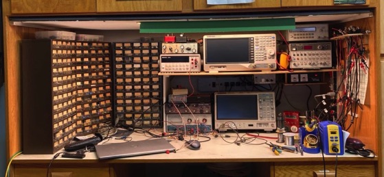
Thanks to Ebay, the hobbyist’s life is now augmented with affordable, though sometimes aging, commercial gear. But also some nice new stuff as well. Here’s what I’m using these days.
Siglent SSA3021+ RF Spectrum Analyzer In 2022, I updated to a fully modern instrument, having previously owned HP 8568B and 8560A instruments.
Siglent SDS2204+ DSO. Also upgraded in 2022, from my previous Tek TDS320 and 2215. This scope has been hacked to enable all its options and increase bandwidth to 500 MHz. Instructions can be found on the EEVblog. Make sure you get good probes for your scope. The ones provided by Siglent are actually very good. I also have some 350 MHz Tek models.
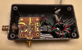
HP 1120A Active Probe For RF circuits with an impedance greater than 50 ohms, a FET probe is very useful. This is an old model but still effective up to 500 MHz. My old HP spectrum analyzers had a probe power jack, but now I use this power supply that I built. It can power all sorts of small amplifiers and accessories: Probe_Power_Supply.pdf
AADE L/C Meter Very affordable and incredibly useful. Sadly, no longer made. There are some Chinese equivalents available on Ebay that are similar and affordable.
HP 5384A Frequency Counter Upgraded to ovenized oscillator. This is my bench 10 MHz reference but its output is only -20 dBm, not enough to drive anything. So I built this simple amplifier that runs off the counter’s raw power supply: 10_MHz_Distribution_Amp.pdf
Rockland (later Wavetek) 852 Active Filter. I use this when making true rms AC measurements on audio-frequency signals, among other things.
HP 3314A Function Generator. A great value; it’s even an ARB.
Heath IP-2718 Power Supply
Agilent 34401A Multimeter. An industry standard. GPIB controlled with LabVIEW for data logging.
Eico 710 Grid Dip Meter. My only tubed item! Still works great. Here is fabrication info on the Eico coils: Eico Coils.pdf
VNWA-3e Vector Network Analyzer. A professional-grade instrument in a tiny USB-powered box, with outstanding software. https://www.sdr-kits.net/.net/
Homebrew Test Equipment
“Make what you use and use what you make.” That’s a quote from Experimental Methods in RF Design (EMRFD), one of my all-time favorite books. It also applies to woodworking, where many tools are easily made or customized to suit the user. By making your equipment, you learn a great deal about its intrinsic capabilities and limitations. You also find out just how hard it is to build very accurate instruments! Your homebrew gear can be as simple and sloppy as a few parts tacked down to copper clad board, or works of art in very fine enclosures. Whatever works; whatever you have time for. Here’s some of my stuff.
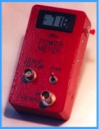
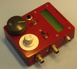
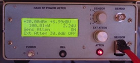
RF Power Meter. This miniature meter is based on a design by Wes Hayward, W7ZOI, and several follow-on adaptions published in QST, QEX, and elsewhere. It’s one of my most-used instruments. Here is a full article on how I built mine. WB9JPS_RF_Power_Meter.pdf It’s the lowest-power, most compact version I’ve seen anywhere.
N2PK Vector Network Analyzer. The ultimate RF system analyzer.... Click the photo to learn all about my version of this instrument. This was the first successful hobbyist VNA, appearing in 2006. See my N2PK Page.
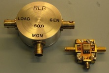
Return-Loss Bridges. When characterizing any RF circuit, the RLB will tell you how good the input or output match is. Designs for RLB are in the ARRL Handbook, EMRFD (p. 7.22), and all over the web. I made one from a bifilar-wound toroid, and the other from a Mini-Circuits T1-1 1:1 transformer. The latter one performed very well out to at least 150 MHz. In any case, build it as compactly as you can, with a shield.
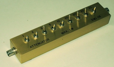
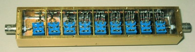
Step Attenuator. I eventually found a really good deal on some commercial rotary-dial type attenuators on Ebay, but the one I built is sure pretty! It’s made from machined brass parts and uses toggle switches. This is the usual design from the ARRL Handbook.
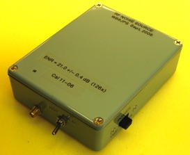
Calibrated RF Noise Source. This is useful if you want to characterize the noise performance of RF amplifiers and systems. The design is by Bill Sabin, W0IYH, and is detailed in EMRFD (p. 7.39). The main thing you need is the noise diode from NoiseCom. The good folks there will give you a great deal if you call and say you’re doing this as a radio amateur. They will also calibrate your instrument for you for $100. That may seem like a lot, but the commercial price for that service is about $800! I calibrated mine from first principles, by comparing its output against a calibrated RF generator at several frequencies. It’s built on a simple surface-mount PC board fabricated by the Sharpie method, and is enclosed in a Hammond aluminum box. I ran mine off of three 9 V batteries in series, with an LM317 voltage regulator set to about 22 V. That way, battery voltage droop won’t bother my calibration. Use of this noise source is discussed in one of my reports: R2Pro_LNA_Performance_1.pdf
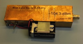
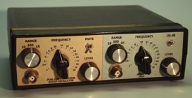
Weak-Signal Generator. When testing a receiver, you eventually need a really low-level signal source with a calibrated output level. Using a high-level source plus massive amounts of attenuation (like 80+ dB) often results in errors due to leakage. So I built this simple crystal oscillator (14.040 MHz) with built-in attenuators into a fully-soldered copper box, and ran it on a 9 V battery. I calibrated it by comparing with another calibrated RF generator. As usual, the design is from EMRFD (p. 7.18).
DDS RF Generator. After trying to use an ancient B&K RF generator for a while, I decided to whip up a simpler but more capable instrument based on a DDS chip. There are several DDS VFO kits on the market; the one I chose, the DDS3 from Tormet Engineering (no longer available). The minimum requirement for me was a way to switch bands and a rotary encoder for tuning, plus a frequency display. The tiny DDS3 had that, and goes up to 50 MHz. Its output feeds a double-balanced mixer so that it can be modulated, producing DSB. The output stage is a wideband opamp (an LMH6703 on its evaluation board) preceded by a 100-ohm pot as the level adjustment. It all fit in a tiny Hammond aluminum box and is powered from a wall-wart. Works great, with reasonably low spurious output. I like these small instruments because a whole bunch of them can sit, interconnected, on my bench.
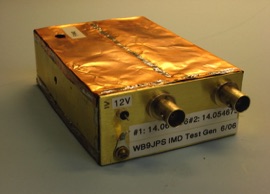
RF Intermod Test Source. Two closely-spaced RF carriers are needed to test intermodulation distortion (IMD) response of RF systems. We usually report the results as a third-order intercept (IP3). The generator I use is a pair of crystal oscillators described in EMRFD (p. 7.19). They are built ugly-style right next to each other with full shielding around each one to avoid any chance of self-intermod. Outputs are buffered with wideband opamps; I get about +3 dBm out of each with low distortion. The sources then feed a Mini-Circuits 2:1 splitter/combiiner, which then feeds the device under test. Having those opamps on the output is a big advantage because their reverse isolation is extremely high. I’ve proven that this simple combination, without any extra attenuators at the outputs, is capable of very high IP3 performance, to at least +40 dBm. Application of this generator is described in one of my reports: R2Pro_LNA_Performance_2.pdf
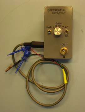
Differential Measuring Amp. I’ve built a couple of these over the years for low-level audio measurements. The idea is to use a differential, or instrumentation, amplifier to amplify the signal while avoiding grounding issues. Both AC and DC coupling, along with accurate gain steps, are very useful. A larger benchtop model that I built also has some filtering built in. The main specifications are low noise, low DC drift, high common-mode rejection, high gain accuracy, and bandwidth sufficient for the audio bands. My latest mini instrument (schematic link at right) is based on an AD524 instrumentation amplifier, which has very low noise and built-in input protection. I include an opamp to drive the input cable’s shield at the common mode voltage. The whole thing runs off of two 9 V batteries and fits in a tiny Hammond aluminum enclosure.
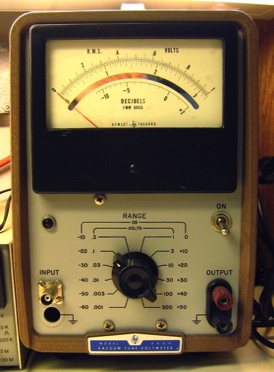
True RMS Voltmeter. Some audio measurements are best made with a true RMS voltmeter, for instance when testing a receiver’s minimum detectable signal (MDS) level. For this instrument, I started with an old HP410 VTVM ($20 on Ebay), and gutted the tube electronics. I reused the case, the range switch and compensated attenuators, and the excellent mirrored-scale meter. The circuit is basically an AD636 true RMS converter chip with a few opamps where gain is needed.
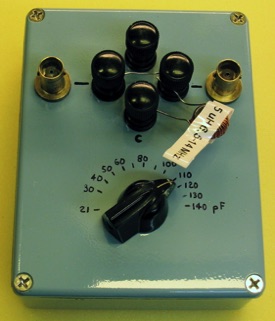
Notch Fillter Box. This simple box is from EMRFD (p. 7.31). It’s nothing more than 20-140 pF air variable capacitor in a box, with one side of the cap grounded. What you do is connect it in series with a fixed inductor, and then connect that series-resonant circuit as a shunt across a signal that is passing through the box. This forms a tunable notch filter. Note that you can use if for other things as well... it’s just a variable cap, after all. Its intended purpose is for suppressing the fundamental when you are trying to measure harmonic distortion, for instance in an amplifier. You drive the amplifier with a signal generator, then put this notch filter after the amplifier, and finally observe the signal on a spectrum analyzer. This keeps the SA from being the main source of harmonic distortion. Note: You should insert an attenuator, 10 dB is good, before the notch filter to keep from “shorting out” the amplifier under test. I get a good 30 to 40 dB notch at 14 MHz or lower, and at least 25 up to 30 MHz with this box.
Ultra-Low Noise Low-Frequency Preamplifier. I was trying to directly measure the noise floor of several voltage regulator/filter combinations. This is a VERY difficult problem because the source impedance is very low, and any preamplifier you use will probably be noisier than the source. But being an old audio guy, I pulled out a favorite moving coil phono cartridge preamp design, by W. Marshall Leach of Georgia Tech. This circuit is simple, and well-optimized for low source impedances. By adjusting the transistor bias currents, you can actually noise-match this amplifier to the source. It ended up with an input resistance of about 26 ohms. I went one step further and added a 4:1 step-up transformer to the input. Since impedance goes as turns squared, the input resistance ended up around 1.2 ohms. To avoid shorting out the DC power source I was trying to measure, I added a large input coupling capacitor. Overall gain is 300, bandwidth is 1 to 600 kHz, and input noise is 0.2 nV/rtHz. That’s equivalent to the thermal noise of a 2.7 ohm resistor!
Wideband Bias Tee. This is a useful test accessory, needed when measuring a device that requires DC bias in the presence of RF. Read about my design on the Bias Tee page. This has turned out to be about the most popular design I’ve ever worked on...
Low-Distortion Audio Oscillator. Here’s a pretty standard Wien bridge oscillator for routine audio testing. Two identical channels, so you can do intermodulation tests with it. This one runs on 12 VDC and uses a DC-DC converter power supply with extensive filtering to make its switching artifacts undetectable in the audio outputs. 1 KHz distortion is about .003% but rises at low frequencies due to the lamp’s thermal time constant.
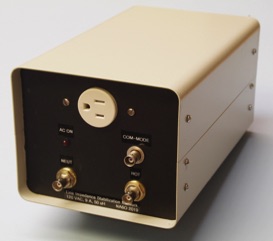
Line Impedance Stabilization Network (LISN). I’ve been doing measurements on devices that generate RFI, and a very useful tool for this is a LISN. It’s basically a lowpass filter for the AC line that rejects noise and provides a constant 50 ohm source to the device under test, along with some measurement ports. This one can be built for about $200 and works up to 125V/9A and 100 MHz. A number of people all over the world have built their own version. Full writeup is here: LISN_by_NA6O.pdf
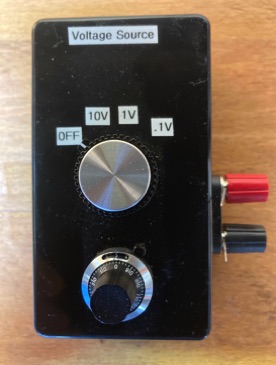
Precision Voltage Source. A small, fairly accurate, battery-powered, variable DC reference source has countless uses. I mostly use it to check A/D inputs and provide a small DC signal for test purposes. It can be accurately set from a few mV to 10 V. This one was hacked together from available components but the plan should give you a starting point for your own design.
Laboratory RF Power Meter. I always wanted a more full-featured power meter, with interchangeable sensors, multiple displays, and computer control. Here’s the complete design for my latest creation. It’s based on a Raspberry Pi controller, programmed in LabVIEW of course, with a nice wideband sensor in a bulletproof enclosure. Full aritlce: RF_Power_Meter_II.pdf
Wideband Buffer Amplifier. Sometimes you need to use a 50-ohm instrument like a spectrum analyzer to measure something that can’t drive 50 ohms. For that, a wideband buffer is useful. Here’s one that uses a fast opamp (LMH6703) to provide flat gain to at least 300 MHz with an input resistance of 5k. It does require bipolar power supplies.
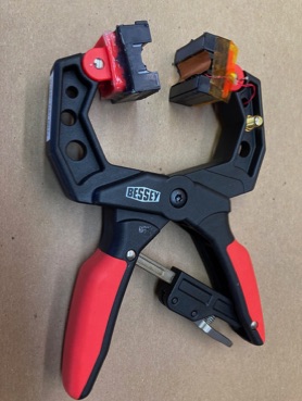
Clamp-on Current Probe. Clamps onto conductors up to 0.45”. Bandwidth 0.15-100 MHz. Zt = 4.5 V/A. Ferrite core is a Fair-Rite 0443164151 with 5 turns of #26 magnet wire. Coil is terminated into a 47 ohm resistor mounted on an SMA jack. A small copper shield is glued over the coil to reduce capacitance a bit. Core halves are glued to the Bessey XCRG2 2” clamp with silicone glue. With reasonable care, this should last a long time. I mainly use this to locate stray RF EMI currents on conductors.
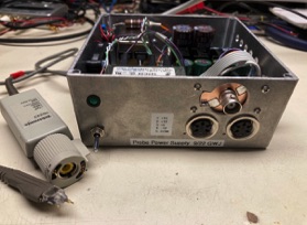
Probe Power Supply. I seem to have several probes that require various DC voltage to operate, and I’m tired of having too many power supplies lying around. Also, I had this nice Tek P6243 FET probe that needs a TekProbe connector... So I solved all those problems by making this do-it-all box. The TekProbe connector is a hand-made PC board. DIN connectors provide +5, +12, +15, and -12V from a hacked Chinese regulator board I found on Amazon. This might give you some ideas...
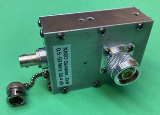
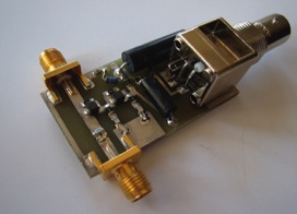
High-power RF Sampler. Useful when observing the output of RF amplifiers. This one works from 0.5 to 50 MHz at up to 2 kW without distortion and has 50.4 dB of attenuation at the sample port. Built from an article by W5QN, who spent the time to get the values right. My main improvement was using a larger core (T200-2) for the toroid to avoid saturation at high power and low frequencies. Also there is a full shield between the toroid and the output matching resistors. All parts are machined.