Design Objectives
After 35 years in high-end audio, I decided to sell off my big, heavy, expensive, power-hungry equipment and simplify my system. Since I’ve also spent these last decades doing electronic engineering (starting with audio while I was in high school in 1975!), a design of my own was in order. Here’s what I wanted:
An integrated amplifier that includes a phono input.
At least 50 W/chan into 8 ohms, but fully rated into 2 ohms.
Reasonably efficient class AB outputs.
Reliable, conservative, robust design that will last “forever.”
Very simple controls: source select, volume, balance, and power.
Headphone output.
Compact, fairly light, and pretty packaging.
Click on the thumbnails at right to download the overall system block diagram and interconnect diagram.
Power Amplifier
I settled on a fairly simple power amplifier topology, using lateral power MOSFETS (Excicon 20N20/20P20) because they are rugged, thermally forgiving, support very high current, and are fun to design with. Modest power supply voltage (±38 V) achieves the desired output power without stressing any components.
For those familiar with such designs, the most interesting point is the frequency compensation scheme. It’s derived from Peter Baxandall’s Inclusive Miller Compensation. This scheme encloses the output stage in the feedback loop over a greater bandwidth than is normally achievable, resulting in lower distortion at high frequencies. In this case, a factor of five better at 20 kHz when compared with conventional Miller compensation of the voltage amplifier stage. More information on this and related compensation techniques is found in Bob Cordell’s excellent book, Designing Audio Power Amplifiers.
Compensation was optimized with the help of my N2PK Vector Network Analyzer. The goal is to achieve maximum loop gain while maintaining sufficient gain and phase margin for stability. Most folks working in audio don’t use such an instrument since it’s nominally for RF design. That’s unfortunate, because it gives the designer an instant and unambiguous view of an amplifier's high-frequency gain and phase. Results can be compared to simulations done in LTSpice or other circuit analysis packages. Simulation, while not terribly accurate in some areas such as these old-school power MOSFETS, is very useful when deciding which component to adjust to achieve a certain result.
When completed, the amplifier specs were as follows:
- 60 W into 8 ohms, and 125 W into 2 ohms.
- THD at 20 kHz: 8 ohms, 0.006%, 4 ohms, 0.025%, 2 ohms, 0.18%.
- 18 A peak into 1 ohm.
- Slew rate 200 V/microsecond
- Continuous operation at 1/3 power into 2 ohms without overheating.
- Unconditionally stable into any reactive load with the addition of a 750nH inductor (not present on the amplifier board).
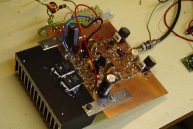
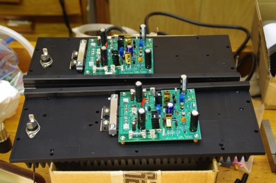
Here’s the “ugly style” prototype and final product.
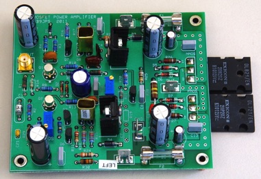
For DIYers out there, here is the PC board design. It was done in ExpressPCB. All boards for the entire system are on a 1-foot square layout, of which I had two fabricated. You can copy and paste parts out of it. Download: Preamp_and_power_amp_ ExpressPCB.pcb
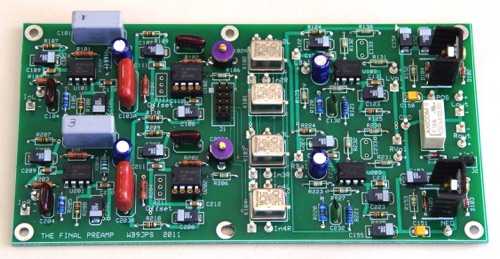
A Simple, Modern Preamp
For my purposes, there’s no reason to go haywire on an over-designed preamp. Modern audio op-amps offer exceptional performance, so that was a slam-dunk decision. My favorite op-amps are LME49710 and the dual LM4562. I find them easier to apply than the AD797, which is exceptionally prone to parasitic oscillation above 10 MHz.
Here are the main features of my preamp:
- Two-stage RIAA phono section with feedback equalization.
- Teledyne 122C military relays for source switching.
- Low overall line section gain (10 dB).
- Step attenuator for volume control.
- The “Better Balance Control” arrangement from ESP Audio.
- Cardas RCA phono jacks connected via micro Teflon coax.
The preamp runs off an independent power supply, with a small toroidal transformer, rectifier, and filter.
Main Power Supply
The main power supply uses an Antek 400 VA toroidal transformer in a steel shield, 35A bridge rectifiers (one for each channel), and 30,000 uF of capacitance for each supply rail. A careful grounding plan was enforced, with a main single-point ground in the middle of the chassis. I also used a “ground break” circuit to separate the signal ground from the safety ground, but without adding a safety hazard.
To limit inrush current, I used a positive tempco inrush limiter with a time-delay relay that shorts it out after a second or so.
Output Protection
For system reliability, I wanted speaker output protection. The best way to do that is to monitor the power amp outputs and use a suitable relay to disconnect the load when DC or a thermal overload is detected. (The power amp protects itself with rail fuses that blow when the output is shorted.) I used a simple, old transistor array for this circuit, the TA7317. It provides a power-on delay, a quick disconnect when power is turned off, and disconnect when signals below about 0.4 Hz are present. The relay was a lucky find on ebay, a very expensive military relay: Deutsch ET4103602BG-D. It’s a high-current 4PDT relay in a hermitic enclosure. Pairs of contacts are used in parallel.
Headphone Amplifier
I’ve always liked to have a convenient headphone jack right on the front panel. This amplifier is a buffered opamp: An LME49710 with an LT1010T buffer. Distortion is below my instrumentation threshold (<0.002%) and it drives 32-ohm headphones easily. It’s also stable into large capacitive loads. It lives on the same board as the preamp power supply.
Fabrication
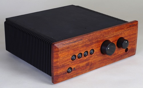
Aluminum and Wood
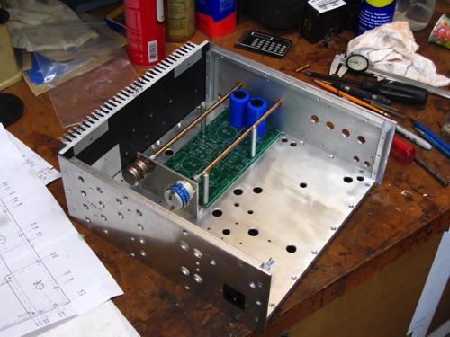
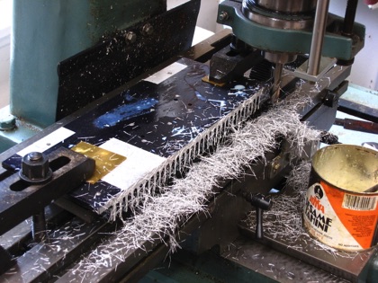
My other hobbies are woodworking and metalworking, so this project’s chassis combines those elements. Parts for the enclosure are 6061-T6 aluminum sheet and bar stock. A bit of CAD drawing helped a great deal because things are packed pretty tight in three dimensions. Everything was fabricated on my Chinese drill-mill, so tolerance nice and tight. Overall dimensions of the box are 12 x 12 x 5.5 inches.
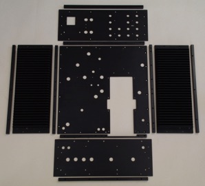
Heatsinks cover both sides of the chassis. I found a 12-inch square extrusion on ebay. It had some holes in it, but otherwise it was a great deal. Top and bottom edges are chamfered and rounded. They look just like my Rowland Model 5 heatsinks...
Everything went to my local anodizing shop. Only about $80 for a bucket of parts. Heatsinks had to be stripped first since they were partially anodized already.
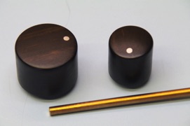
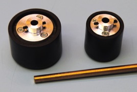
Knobs are Gabon Ebony with hubs turned from aluminum. Shafts are 1/4” bronze. Using long shafts allows me to put the pots by the electronics, thus reducing wire lengths.
Here is assembly work in progress. Most of the wiring is under the chassis plate for a clean look.
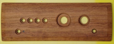
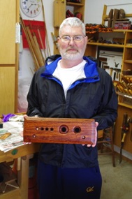
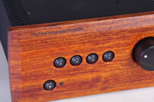
The front panel is figured Bubinga. My good woodworking friend, Bruce Woods, gave me this material. Sadly, he passed away shortly after I took this photo of him. I miss him very much.
Labels were laser-etched at a local trophy shop.
Power amplifier boards bolt to the heatsinks. Silpad K-10 (6 mil) material is under the MOSFETS and heavy bars create uniform pressure, no matter what. There are NO thermal issues.
Gallery
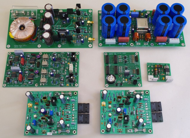
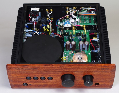
Boards, clockwise from top left: Preamp PS/headphone amp; main power supply and protection; Mode control; time-delay relay driver; two power amps; preamp.
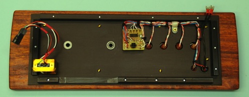
Behind the front panel. Headphone jack has an optical chopper switch to detect phone plug insertion.
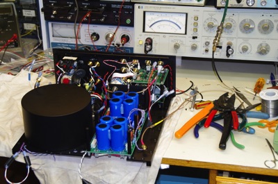
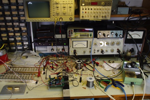
Testing a power amp module. I convert my test equipment suite between RF and audio/instrumentation configurations as needed; there’s not that much room!
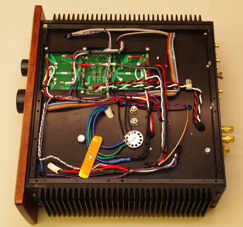
Bottom view. The star ground is the silver ring near the bottom. That's the power supply board peeking through a hole in the bottom plate.

Oh, by the way, it sounds as good as it looks. If it weren’t for my hearing troubles (due to an acoustic neuroma) I would give it a more formal audiophile-style review. Dynamics are excellent, plenty of “slam” when driving my Thiel CS 3.6s, which are basically 2-ohm loads. And no clicks, thumps, buzz, hum, or anything else. Victory. This remains the finest electro-mechanical design I've ever produced. And indeed, it is my Final Integrated Amplifier.